| Contact Us for Quotation | Email:464560351@qq.com | Whatsapp: +8618620373879 |
Product Introduction
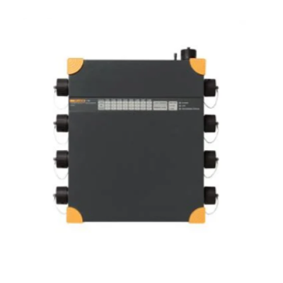
| The TesterMeter-Fluke 1760 Three-Phase Power Quality Recorder is fully compliant to IEC 61000-4-30 Class-A, for advanced power quality analysis and consistent compliance testing. Designed for analysis of utility and industrial power distribution systems, in medium- and low-voltage networks. The Fluke 1760 provides exceptional flexibility with the ability to customize thresholds, algorithms, and measurement selections. The 1760 power recorder captures the most comprehensive details on user-selected parameters; the supplied PQAnalyze application software enables users uses the in depth measurement and produce sophisticated analysis and reports. |
Applications
|
Specifications
| Overview of Measurement Functions | |||
| Statistical evaluation | Power quality statistics according to EN50160 and DISDIP tables like ITIC, CEBEMA, ANSI | ||
| Event list | Dips, swells and interruptions are detected and stored in the event list. Also any trigger which fires generates an event added to this list. | ||
| The Event list shows the exact time when the event occurred as well as the duration and magnitude. Sorting by several attributes of these events is possible to select one for further root cause analysis. | |||
| RMS values, transients and fast transients can be stored if a trigger fires | |||
| Continuous recording | Fluke 1760 records rms values together with corresponding minimum and maximum values for: • Voltage • Current • Power P, Q, S • Power Factor • kWh • Flicker • Unbalance • Frequency • Harmonics/Interharmonics continuously with the following time aggregations: Day, 10 min, Free Interval, e.g.: 15 min, 2 h | ||
| Triggered recordings | rms | Aggregation time is adjustable between 10 ms (1/2 cycle), 20 ms (1 cycle), 200 ms (10/12 cycles) or 3 sec (150/180 cycles). | |
| Calculating rms values, Harmonics and Interharmonics is performed synchronous to the power frequency. | |||
| Basic aggregation for harmonics and interharmonics is 200 ms | |||
| Oscilloscope | Sample rate is 10.24 kHz for all 8 channels | ||
| Mains signalling | Phases and N-conductor, Voltage and current | ||
| Online mode | Variable refresh rate. This feature allows verification of instrument set up and delivers a quick overview of oscilloscope, transients and events. | ||
| General Data | |||
| Intrinsic uncertainty | refers to reference conditions and is guaranteed for two years | ||
| Quality system | developed, manufactured as per ISO 9001: 2000 | ||
| Environment conditions | Operating temp. range | 0°C to +50°C; 32°F to +122°F | |
| Working temp. range | -20°C to +50°C; -4°F to +122°F | ||
| Storage temp. range | 20°C to +60°C; -4°F to 140°F | ||
| Reference temperature | 23°C ±2 K; 74°F ±2 K | ||
| Climatic class | B2 (IEC 654-1), -20°C to +50°C; -4°F to +122°F | ||
| Max. operating altitude | 2000 m: max. 600 V CAT IV1, power supply: 300 V CAT III 5000 m: max 600 V CAT III1, power supply: 300 V CAT II | ||
| 1. depending on sensor | |||
| Reference conditions | Environment temp. | 23°C ±2 K ; 74°F ±2 K | |
| Power supply | 230 V ±10% | ||
| Power frequency | 50 Hz / 60 Hz | ||
| Signal | declared input voltage Udin | ||
| Averaging | 10 minute intervals | ||
| Housing | Insulated, robust plastics housing | ||
| EMC | Emission | Class-A as per IEC/EN 61326-1 | |
| Immunity | IEC/EN 61326-1 | ||
| Power supply | Range | AC: 83 V to 264 V, 45 to 65 Hz | |
| DC: 100 V to 375 V | |||
| Safety | IEC/EN 61010-1 2nd edition | ||
| 300 V CAT III | |||
| Power consumption | NIMH, 7.2 V, 2.7 Ah | ||
| Battery pack | In case of a power supply failure an internal battery maintains the supply for up to 40 minutes. Afterwards, or in case of discharged accumulators the Fluke 1760 is turned off and continues the measurements with the latest settings as soon as the supply voltage returns. The battery can be replaced by the user. | ||
| Display | Fluke 1760 features LED indicators for the status of the 8 channels, phase sequence, power supply (mains or accumulator), memory usage, time synchronization, and data transfer. | ||
| Power LED | Permanent light: normal power supply from mains. OFF: supply via internal accumulator in case of a power failure. | ||
| Channel LEDs 3-color LEDs per channel for | Overload condition Under load condition | ||
| Data memory | 2 GB Flash memory depending on model | ||
| Memory model | Linear | ||
| Interfaces | Ethernet (100 MB/s), compatible to Windows® 98/ME/NT/2000/XP RS 232, external modem via RS 232 | ||
| Baud rate for RS 232 | 9600 Baud to 115 kBaud | ||
| Dimensions (H x W x D) | 325 x 300 x 65 mm; 2.8 x 11.8 x 2.6 in | ||
| Weight | appr. 4.9 kg; 10.8 lbs (without accessories) | ||
| Warranty | 2 years | ||
| Calibration interval | 1 year recommended for Class-A, otherwise 2 years | ||
| Signal Conditioning | |||
| Range for 50 Hz systems | 50 Hz ±15% (42.5 Hz to 57.5 Hz) | ||
| Range for 60 Hz systems | 60 Hz ±15% (51 Hz to 69 Hz) | ||
| Resolution | 16 ppm | ||
| Sampling frequency for 50 Hz power frequency | 10.24 kHz, The sampling rate is synchronized to mains frequency. | ||
| Uncertainty for frequency measurements | < 20 ppm | ||
| Uncertainty of internal clock | < 1s / day | ||
| Measurement intervals | Aggregation of the interval values as per IEC 61000-4-30 Class-A | ||
| Min-, Max-values | Half cycle, e.g.: 10 ms rms values at 50Hz | ||
| Transients | Sample rate 100 kHz to 10 MHz per channel | ||
| Harmonics | as per IEC 61000-4-7:2002: 200 ms | ||
| Flicker | as per EN 61000-4-15:2003: 10 min (Pst), 2 h (Plt) | ||
| Measurement Inputs | |||
| Number of inputs | 8 galvanically isolated inputs for voltage and current measurements. | ||
| Sensor safety | up to 600 V CAT IV depending on sensor | ||
| Basic safety | 300 V CAT III | ||
| Nominal voltage (rms) | 100 mV | ||
| Range (peak value) | 280 mV | ||
| Overload capacity (rms) | 1000 V, continuously | ||
| Voltage rise rate | max. 15 kV / µs | ||
| Input resistance | 1 MΩ | ||
| Input capacitance | 5 pF | ||
| Input filter | Each channel is equipped with a passive low-pass filter, an anti-aliasing filter and a 16-bit A/D converter. All channels are sampled synchronously with a common quartz-controlled clock pulse. The filters protect against voltage transients and limit the signal rise rate, reduce high frequency components and especially the noise voltage above half the sampling rate of the A/D converter by 80 dB, thus achieving very small measuring errors in an exceptionally large amplitude range. This is also valid under extreme operating conditions like transient voltages at the output of converters. | ||
| Uncertainties | |||
| Uncertainty at reference conditions | Uncertainty including the voltage sensors is in compliance with IEC 61000-4-30 Class-A. All voltage sensors are suitable for DC up to 5 kHz | ||
| With Sensor 1000 V | 0,1% at Udin = 480 V and 600 V P-N | ||
| Sensor 600 V | 0,1% at Udin = 230 V P-N | ||
| Intrinsic uncertainty for harmonics | Class I as per EN 61000-4-7:2002 | ||
| Reference conditions | 23°C ±2 K < 60% rH; 74°F ±2 K < 60% rH | ||
| Warmed up instrument > 3h | |||
| Power supply: 100 V to 250 V AC | |||
| Temperature drift | 100 ppm / K | ||
| Aging | < 0.05% / year | ||
| Common mode rejection | > 100 dB at 50 Hz | ||
| Temperature drift | Change of amplification through temperature: < 0.005%/K | ||
| Aging | Change of amplification due to ageing: < 0.04%/year | ||
| Noise | Noise voltage, input short-circuited: < 40 µV | ||
| DC | ±(0.2% rdg + 0.1% sensor) | ||


 English
